
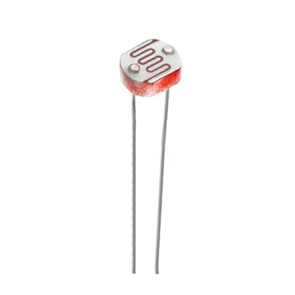
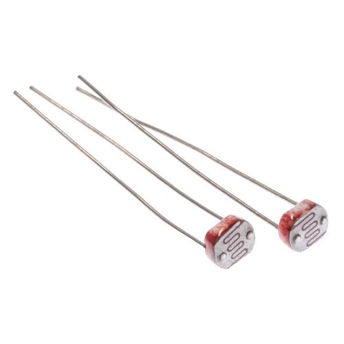


5mm LDR Light Sensors

₵5.00
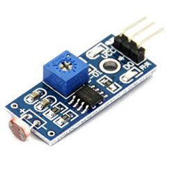
The 5mm LDR (Light Dependent Resistor), also known as a photoresistor or photocell, is a simple, two-pin, passive component whose resistance changes dramatically based on the intensity of light falling upon its surface. The 5mm specification refers to the typical diameter of the light-sensitive disc component.
60 in stock
Operating Principle
The 5mm LDR operates on the principle of photoconductivity:
- Material: It is typically made from a semiconductor material, such as Cadmium Sulfide ($\text{CdS}$), which is sensitive to visible light (often peaking around $540\text{ nm}$, similar to the human eye).
- In Darkness: In the absence of light, the material has very few free charge carriers (electrons), resulting in very high electrical resistance (the Dark Resistance), often in the range of $1\text{ M}\Omega$ to $20\text{ M}\Omega$.
- In Light: When photons from incident light strike the semiconductor material, they transfer energy, knocking electrons from the valence band into the conduction band. This creates electron-hole pairs, which are free charge carriers.
- Resistance Change: The increase in free charge carriers leads to a large increase in the material’s conductivity and a sharp decrease in electrical resistance. In bright light (e.g., $10\text{ Lux}$), the resistance drops significantly, typically to $10\text{ k}\Omega$ to $20\text{ k}\Omega$.
Key Relationship: $\text{Higher Light Intensity} \implies \text{Lower Resistance}$
Typical Specifications
The 5528 model is one of the most common 5mm LDR types in hobbyist electronics.
| Feature | Typical Value / Range |
| Size/Mounting | $5\text{ mm}$ Diameter, Through-Hole (2 pins) |
| Material | Cadmium Sulfide ($\text{CdS}$) |
| Max Voltage | $150\text{V}$ DC |
| Max Power Dissipation | $100\text{ mW}$ to $200\text{ mW}$ |
| Dark Resistance | $\ge 1\text{ M}\Omega$ |
| Light Resistance ($\text{10 Lux}$) | $10\text{ k}\Omega$ to $20\text{ k}\Omega$ |
| Spectral Peak | $\approx 540\text{ nm}$ |
Interfacing with Microcontrollers (Voltage Divider)
Since a microcontroller’s Analog-to-Digital Converter (ADC) can only measure voltage, not resistance directly, the LDR is typically integrated into a voltage divider circuit to convert the resistance change into a measurable voltage change.
- The LDR is placed in series with a fixed resistor (often $10\text{ k}\Omega$).
- The series combination is connected across the supply voltage (e.g., $5\text{V}$ from Arduino).
- The analog output voltage ($\text{V}_{\text{OUT}}$) is read at the junction between the LDR and the fixed resistor.
- Dark Conditions: LDR resistance is high, pulling $\text{V}_{\text{OUT}}$ low (close to $0\text{V}$).
- Bright Conditions: LDR resistance is low, pulling $\text{V}_{\text{OUT}}$ high (close to $5\text{V}$).
Common Applications
- Automatic Streetlights: Used to turn lights on at dusk and off at dawn.
- Security Systems: Used as a simple beam-breaker sensor for burglar alarms.
- Camera Exposure Control: Measures ambient light for automatic shutter speed adjustment.
- DIY Projects: Simple light meters, ambient light-controlled toys, and nightlight
Be the first to review “5mm LDR Light Sensors”
Related products

Reviews
There are no reviews yet.