
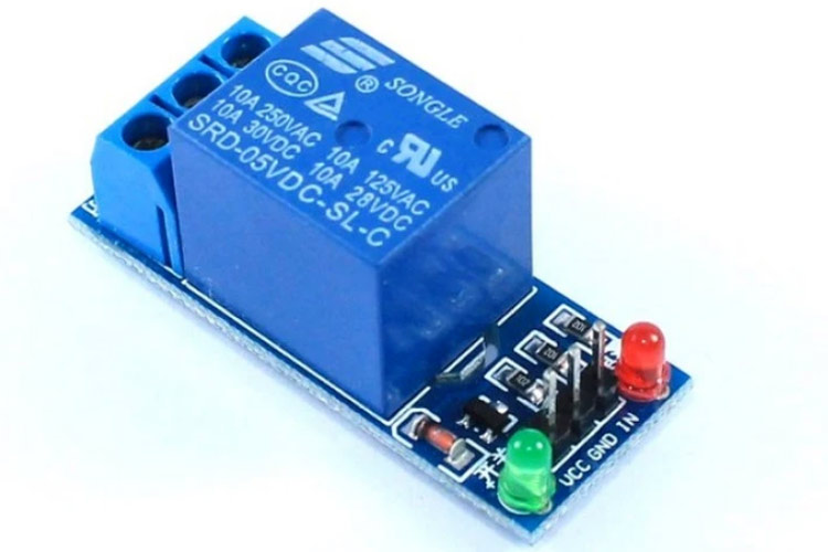

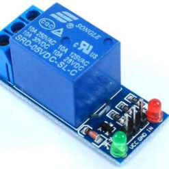
5V Single Channel RELAY Module
₵20.00
Safely control high-voltage and high-current devices with your low-voltage microcontroller using this 5V Single-Channel Relay Module. This module acts as an electrically operated switch, allowing your Arduino, ESP32, Raspberry Pi, or other 5V logic microcontroller to turn on or off devices like lights, fans, motors, and other home appliances.
It provides complete electrical isolation between your delicate microcontroller and the high-power device you are controlling, protecting your project from dangerous voltage spikes.
13 in stock
How It Works
A relay is a simple electromagnetic switch.
- You send a 5V logic signal (HIGH or LOW, depending on the module) to the IN pin from your microcontroller.
- This signal activates a transistor, which energises an electromagnet (the coil) inside the relay.
- The magnetic field pulls a mechanical switch, instantly connecting or disconnecting the high-power circuit connected to the screw terminals.
- Most modules include an optocoupler, which uses light to send the signal, creating a physical gap that electrically isolates your control circuit (microcontroller) from the load circuit (appliance).
Key Features
- 5V Logic Control: Easily triggered by the digital output pins of most common microcontrollers.
- High-Current Load: Capable of switching loads up to 10A at 250VAC or 10A at 30VDC.
- Optically Isolated: An onboard optocoupler (like the PC817 or EL817) protects your microcontroller from the high-voltage side.
- Status Indicator LEDs: Includes two onboard LEDs:
- Power LED (Red): Lights up when the module is powered (VCC/GND).
- Relay Status LED (Green/Blue): Lights up when the relay is active (triggered).
- Secure Screw Terminals: Provides robust and easy-to-use connections for your high-power load wires.
- Freewheeling Diode: Protects your circuit from voltage spikes (back-EMF) generated when the relay coil is de-energised.
Understanding the Pinout
Low-Voltage Control Side (3 Pins):
- VCC: Connects to the 5V power supply from your microcontroller.
- GND: Connects to the Ground (GND) of your microcontroller.
- IN: The control signal pin. Connects to a digital output pin on your microcontroller.
High-Voltage Load Side (3 Screw Terminals):
- COM (Common): The central pin. This is typically where you connect the “live” wire from your appliance or power source.
- NC (Normally Closed): This contact is connected to COM by default (when the relay is off). The circuit is complete.
- NO (Normally Open): This contact is disconnected from COM by default (when the relay is off). The circuit is broken.
How to use NO/NC:
- To turn a device ON when you trigger the relay (e.g., a light), connect your circuit using COM and NO.
- To turn a device OFF when you trigger the relay, connect your circuit using COM and NC.
Common Applications
- Home Automation: Control AC lights, fans, and coffee makers.
- IoT Projects: Build smart plugs or web-controlled switches.
- Robotics: Control high-power motors and actuators.
- DIY Projects: Safely switch any high-voltage or high-current device.
Technical Specifications
- Control Voltage (VCC): 5V DC
- Trigger Current: 15-20mA
- Max Load Rating: 10A 250VAC / 10A 30VDC
- Switching Time: ~10ms
- Module Dimensions: (Typical dimensions, e.g., 43mm x 17mm x 19mm)
What’s Included
- 1 x 5V Single-Channel Relay Module
Be the first to review “5V Single Channel RELAY Module”
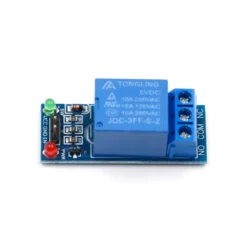
Related products
-8%
Original price was: ₵65.00.₵60.00Current price is: ₵60.00.
-14%
Original price was: ₵110.00.₵95.00Current price is: ₵95.00.
-10%
Out of stock
-13%
Reviews
There are no reviews yet.