
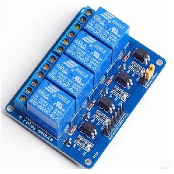

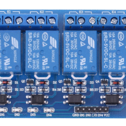
Key Features
- Four Channels: Control four appliances independently.
- High-Current Relay: Each relay is typically rated for 10A at 250V AC or 10A at 30V DC.
- Optically Isolated: Protects your microcontroller from high-voltage surges.
- Status LEDs: Includes individual LEDs for power (Red) and for each relay (Green) to show when it’s active.
- Active LOW Trigger: The relays are typically “Active LOW.” This means you send a LOW (0V) signal from your microcontroller to
IN1to turn the relay ON. - VCC/JD-VCC Jumper: A key safety feature that allows you to provide a separate, isolated power source to the relay coils, further protecting your microcontroller.
Technical Specifications
| Feature | Specification |
| Model | 4-Channel Relay Module |
| Logic (VCC) Voltage | 5V (for the logic chip) |
| Relay Coil Voltage | 5V (powered by JD-VCC) |
| Trigger Signal | 3.3V & 5V compatible |
| Trigger Type | Active LOW (GND signal turns relay ON) |
| Relay Max Rating | 10A @ 250VAC / 10A @ 30VDC |
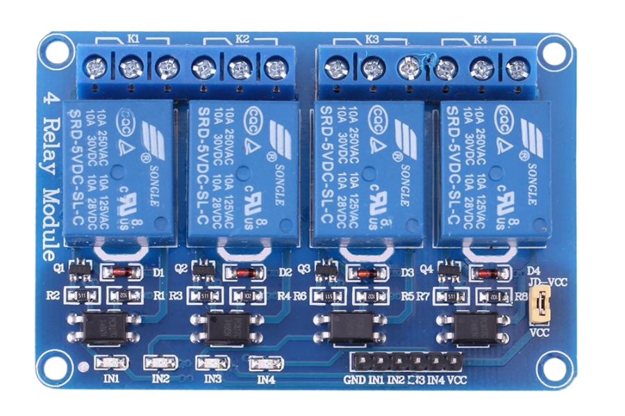
How to Use & Wiring
There are two sides to this board: the high-power “load” side and the low-power “control” side.
1. High-Power Side (The Load)
This is where you connect the device you want to control (like a pump or light). Each of the four green terminal blocks has three connections:
- NC (Normally Closed): The device is ON by default and turns OFF when you trigger the relay.
- COM (Common): The “common” pin. This is where you usually connect the main power wire from your device or power source.
- NO (Normally Open): The device is OFF by default and turns ON when you trigger the relay. This is the one you will use 99% of the time.
Example: Controlling a 220V AC Light Bulb:
- Cut one of the two wires of the light bulb’s power cord.
- Connect one end of the cut wire to the COM terminal.
- Connect the other end of the cut wire to the NO terminal.
- Leave the
NCterminal empty.
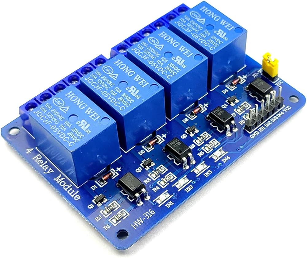
2. Low-Power Side (The Microcontroller)
This 6-pin header connects to your Arduino or ESP32.
- GND: Connect to your microcontroller’s GND.
- IN1: Connect to a digital pin to control Relay 1.
- IN2: Connect to a digital pin to control Relay 2.
- IN3: Connect to a digital pin to control Relay 3.
- IN4: Connect to a digital pin to control Relay 4.
- VCC: Connect to your microcontroller’s 5V pin (This powers the optocouplers).
3. The VCC / JD-VCC Jumper (Important!)
This is the most important part for safety. This jumper connects VCC (logic power) to JD-VCC (relay coil power).
- Jumper ON (Easy Mode):
- Leave the yellow jumper in place.
- Your microcontroller’s 5V pin powers both the logic and the noisy relay coils.
- Risk: This can send electrical noise back to your microcontroller, causing it to crash or reset.
- Jumper OFF (Safe / Isolated Mode – Recommended):
- Remove the jumper.
- You now have three pins:
VCC,JD-VCC, andGND. - To your Arduino: Connect VCC (to 5V) and GND (to GND).
- To a separate 5V Power Supply: Connect JD-VCC (to 5V) and the GND pin next to it.
- This way, your Arduino powers the logic, and the separate supply handles the “dirty” work of powering the relays, giving you full isolation.
Be the first to review “4 Channel Relay Module”
Related products
-20%
-9%
-14%
Original price was: ₵110.00.₵95.00Current price is: ₵95.00.

Out of stock
-4%
Out of stock
Original price was: ₵120.00.₵115.00Current price is: ₵115.00.
-8%
Original price was: ₵65.00.₵60.00Current price is: ₵60.00.
Reviews
There are no reviews yet.