
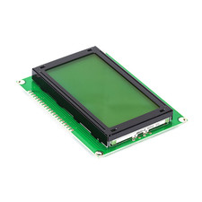


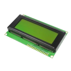
128×64 Dots Graphic LCD (Green)


₵95.00
The 128×64 Graphic LCD provides a large viewing area capable of displaying custom graphics, bitmaps, and varied font sizes. With its classic green backlight, it offers excellent visibility and contrast for your user interfaces.
Fully compatible with the popular u8glib or u8g2 Arduino libraries for easy graphics rendering.
3 in stock
This type of display is commonly driven by one of two popular controllers: the ST7920 (which supports parallel and serial/SPI interfaces) or the KS0108 (which is parallel-only). The ST7920 version is particularly popular with microcontrollers as it can be driven using just a few SPI pins.
Key Features
- Graphic Resolution: 128 x 64 dots, providing a large area for detailed graphics.
- High Visibility: Features a bright yellow-green backlight.
- Flexible Interface: Commonly uses the ST7920 controller, which can be set to 8-bit, 4-bit, or a 3-wire Serial (SPI) mode to save pins. (Note: Older models may use the KS0108 controller, which requires a full parallel interface).
- Built-in Character Set: The ST7920 version includes a built-in character ROM (CGROM) with ASCII and basic Chinese characters, making it easy to display text and graphics.
Technical Specifications
| Feature | Specification |
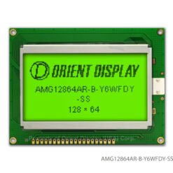
| Model | 12864G |
| Resolution | 128 x 64 Pixels |
| Controller | ST7920 (Common) or KS0108 (Check your model) |
| Interface | Parallel (8-bit/4-bit) / Serial (SPI) |
| Operating Voltage | 5V DC (Common, some models are 3.3V) |
| Backlight | Yellow-Green LED |
| Module Size (Approx.) | 93mm x 70mm |
| Viewing Area (Approx.) | 72mm x 40mm |
| Pinout | Standard 20-pin header |
How to Use & Wiring
This module typically has a 20-pin header. The wiring depends entirely on which controller chip your board has (ST7920 or KS0108).
1. If using an ST7920 Controller (Recommended Mode):
You can use the fast and pin-saving SPI (serial) mode.
- PSB (Pin 15): Connect to GND to select Serial Mode.
- VCC/GND: Connect to 5V and GND.
- V0 (Pin 3): Connect to the middle pin of a 10K potentiometer (with the other legs to 5V and GND) to adjust contrast.
- SCLK (Pin 18 / E): Connect to your microcontroller’s SPI Clock pin.
- SID (Pin 17 / R/W): Connect to your microcontroller’s SPI Data (MOSI) pin.
- CS (Pin 16 / RS): Connect to your microcontroller’s Chip Select (CS) pin.
2. If using a KS0108 Controller (Parallel Mode):
This mode requires many more pins.
- VCC/GND/V0: Wire as above for power and contrast.
- D0 – D7 (Pins 7-14): Connect to 8 digital pins on your microcontroller.
- RS, R/W, E (Pins 4-6): Connect to 3 digital pins.
- CS1, CS2 (Pins 15-16): Connect to 2 digital pins to select the left/right half of the screen.
Crucial First Step: Always confirm your controller chip. The code and libraries for the ST7920 (like the U8g2 library) are completely different from the KS0108 (like the GLCD library).
Be the first to review “128×64 Dots Graphic LCD (Green)”
Related products


Reviews
There are no reviews yet.